Tow Hook 3D modeling Tutorial in Solid Works:
- Select
and click on
.
- Draw Center line of 60mm horizontally starting from origin as shown in Fig. 1.
- Offset the Center line by 32.5 mm using
command. Check mark Bi-directional and Cap ends options as shown in Fig. 1.
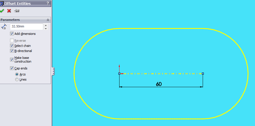
Fig. 1
- Delete the left side half circle and add Vertical Relation in upper and lower points with respect to origin. For this select three points as shown in Fig.2 and click on Vertical in Properties Manager. Now exit from Sketch by clicking on
.
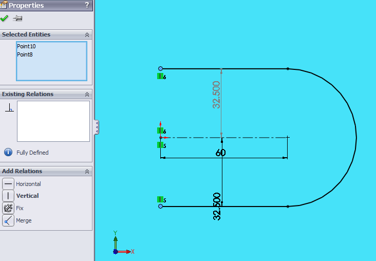
Fig.2
- Select
and Click on
. Draw circles of Diameter 20mm and as shown in Fig.3 using
command.
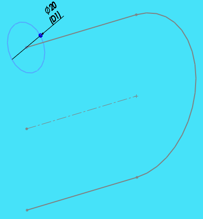
Fig.3
- Make a Swept Profile by using
Command as shown in Fig. 4

Fig.4
- Select
and Click on
. Make the section as shown in Fig.5 using
or
Commands.
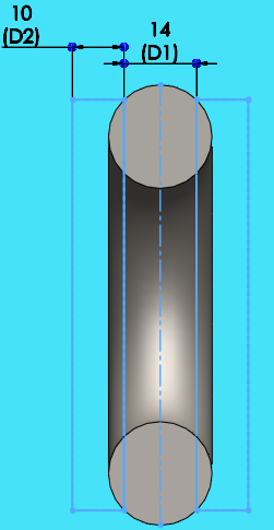
Fig.5
- Cut the selected profile by 50mm as shown in Fig.6 using
command.

Fig.6
- Remove the sharp edges with Fillets of 5mm & 1mm on the corners as shown in Fig.7, 8 and 9 with
command.
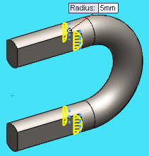
Fig.7
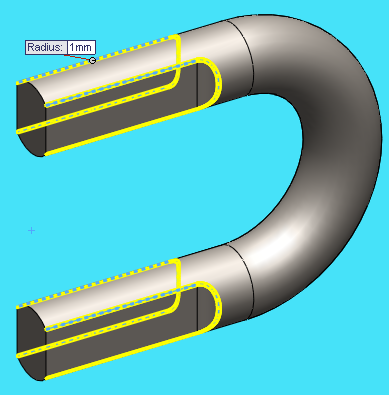
Fig.8
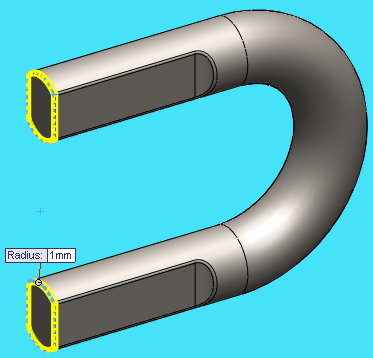
Fig.9
- Select
and Click on
. Draw 2 circles of Diameter 10.5mm as shown in Fig.10 using
command.
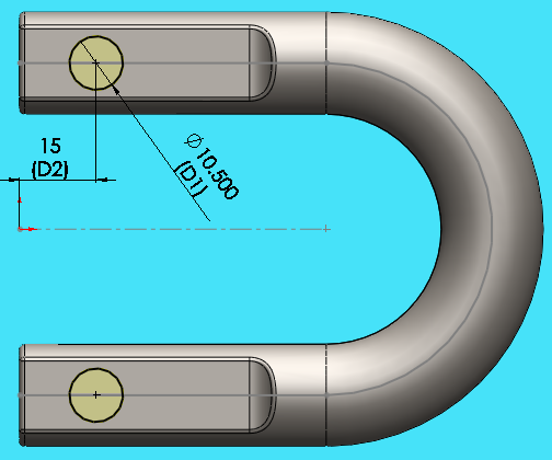
Fig.10
- Make 2 holes using Through All option in both direction 1&2 as shown in Fig.11 using
command.
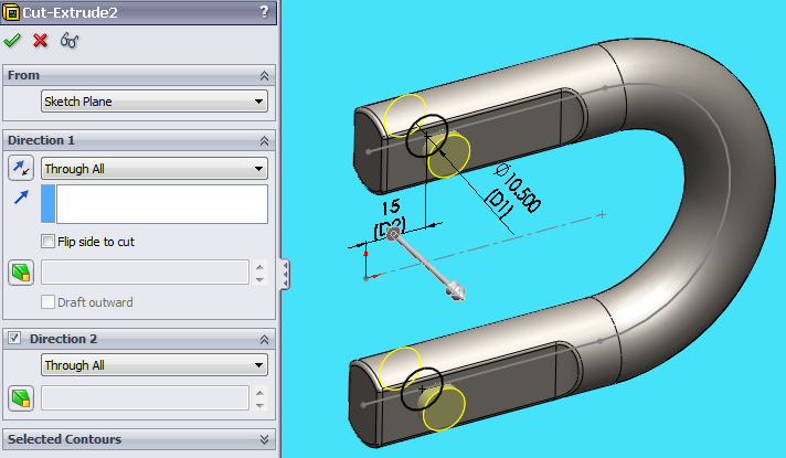
Fig.11
- Remove the sharp edges on Holes as shown in Fig.12 using
Command.
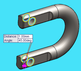
Fig.12
- Select
and Click on
. Draw the profile as shown in Fig.13
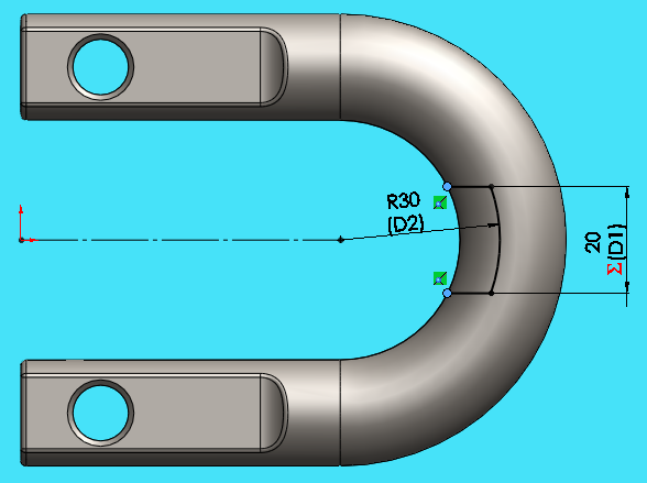
Fig.13
- Split the surface using
command. Use the sketch made in Fig.13 and select the face as shown in Fig.14
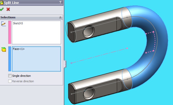
Fig.14
- Now the Tow Hook is ready as shown in Fig.15.
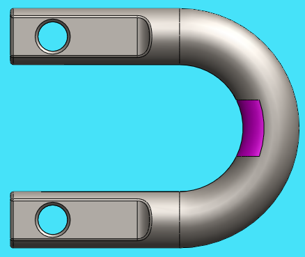
Fig.15
We can use this model for Stress analysis in Solid Works as well as in other FEA analysis software’s like Ansys, Hyper Works etc.
The FEA Analysis in Solid Works of This Tow Hook is coming soon........Stay Tuned........